 |
 |
 |
 |
 |
 |
|
Computerized Trigger and Spring Analysis
|
We would like to give a short overview over the TriggerScan System, what it can do and how to use it. A more detailed information and videos of the TriggerScan System are available here:
|
||
| The System can |
|
||
 |
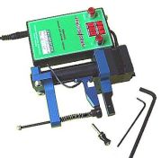
The sensor arm is motorized and measures force during forward and/or backward motion. |
||
| The Software |
|
||
|
The Work Area
|
Control buttons for all frequent tasks are arranged in the work area, and are mouse clickable. .
The test results are shown in columns on the right side. Two measurements can be evaluated at a time (e.g. Single Action and Double Action).
|
||
| The measured data can be: |
|
||
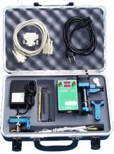 |
The system comes with all necessary components, cables, adapters and tools in a carry case.
|
||
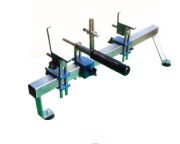 |
The fixture accommodates firearms of all kinds. When the system is used for spring testing the fixture holds the instrument and the spring adapter in position. It can be adjusted for small pistols as well as for large match rifles. |
||
| Reaction Time / Lock Time |
The reaction or lock time* is measured with a probe inserted into the barrel. The exit of the firing pin from the breech face is detected. The time will be displayed in the XX,X format in milliseconds. This capability can also be used if switches or mechanical activated contacts should be tested for the activation timing. * The lock time is defined as the time between a significant drop in force (i.e. the release of the trigger or movement of a switch) and the closing of a contact (i.e. exiting of the firing pin from the breech face or another connection). |
||
Trigger testing |
|||
| The data of the trigger pull will be analyzed for: |
|
||
 |
The arms of the instrument are placed in between the trigger and the trigger guard. The fixed arm rests against the trigger guard, while the moving arm compresses the trigger. |
||
| The measured data can be: |
|
||
| What information can the system analyze on a trigger? |
The system measures the force versus travel
The force on the trigger, that is returning it to his home position, can be of interest for the evaluation of so called release triggers. It is also useful to ensure the proper function of commonly used trigger systems. The necessary balance between enough force to overcome dirt and a moderate trigger pull can be established on scientific measurements. |
||
Testing springs |
|||
 |
The measuring instrument can be easily adapted for spring measurement. The necessary tools and parts are part of the Trigger Scan system. With the standard adapter coil springs can be tested. |
||
 |
The graph shows a compression profile of a tested spring as force versus travel. The spring characteristic is easy to recongise and deviation can can be detected immediately. Additionally the cursor will show its force and travel properties at all positions on the screen. |
||
| The spring data will be analyzed for: |
The system can compress a spring to a determined distance or until a set force is reached. With these features a simulation of the actual working condition of the spring is possible.
|
||
| Home | ||
|
|
||
|
European Distributor for the TriggerScan System
|
Axel Manthei Albrecht-Nützel-Weg 29 |
Tel. +49-(0)8191-66704 E-Mail |